Monday, August 8, 2011

SC944-05

Scientific Conversions SC944-05

SC944-05LF Top View


SC944-05LF Bottom View


SC944-05 is a handcrafted transformer made by Scientific Conversions. The suffix LF stands for Lead Free.

SC944-05 Waveform

SC944-05 @ 200mv/100ns Div


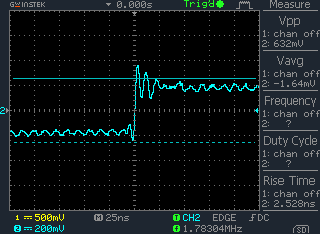
SC944-05 @ 200mv/50ns Div


SC944-05 @ 200mv/25ns Div


Since the Vpp of the original waveform is around 3.3V, with PE65612 (1:1), I have to use resistors to decrease the output voltage level to 600mV. In the test above, those resistors were not removed, I think that's why the peak will be lower than the second one. If the listening experience is better than PE65612, I'll remove those resistors since they are no longer required due to SC944-05's primary/secondary ratio - 2:1.

PE65612 Waveform

PE65612 @ 200mV 25ns


Obviously, SC944-05 has less noise than PE65612 with nearly the same rise time. However, the jitter is not something we can see directly from the oscilloscope, but I believe that my ears will tell.

Listening and Conclusion

The listening experience of the SC944-05 is all positive, better resolution, more clear and accurate bass and the harmonics compare to PE65612.

I'm pretty sure that I'l never go back to PE65612 definitely!


Note for Usage

The pinout for SC944-05 is almost the same with PE65612, you can replace Pe65612 with SC944-05 directly except for SC944-05 needs an additional hole for its pin 2.

The pin 2 is for "shielding", which connects to the shield between the primary and secondary coils.
Th shielding will greatly improve the noise suppression, hence, except for creating an additional hole for SC944-05 while replacing the PE65612, remember to connect the pin 2 of the SC944-05 to the ground of the primary on transmitter side, and to the secondary ground if used on the digital receiver side.

Updates

After 3 hours running-in, I got new conclusion:

PE 65612 is NOT comparable to SC944-05, they are not at the same level!

Friday, August 5, 2011

PE65612 vs. S22083/S22160

Newava S22083 / S22160

I did a simple comparison on my current transportation system for Pulse Engineering Pe65612 and Newava S22083 / S22160. Here's the result.


Waveforms

Newava S22083


Newava S22160


Pulse Engineering PE65612

Listening

ON MY SYSTEM, both Newava S22083 and S22160 sounds worse than PE65612 which matched the waveform result. Not only less resolution but also more noise introduced.

Additional Informration

Thanks to Dr. Jon Paul, who gave me some hints and recommendation with similar results.
See Dr. Jon Paul's AES 2003 paper here.

Wednesday, August 3, 2011

Delta vs. Samsung

Apple Airport Express 802.11n

Open the AAE, you may find that, even with the same AAE model, the factory AAE equipped with different switching power supply modules.

I found that there are at least two switching power supply models.

DELTA Module

Samsung Module

Delta vs. Samsung

Delta @ 2.5 ms


Samsung @ 2.5 ms


Delta @ 1ms


Samsung @ 1ms


The listening experience is the same as the waveform, AAE with Delta module sounds better than Samsung module. This implies that different AAEs (with the same model, 802.11n) may sound different even without modification.

Monday, August 1, 2011

PO74G38072 and DSIX

The Unsolved Misery

Why the PO74G38072 sounds worse than the DISX with TC74VHCU04/PO74G04 ?

This is the question comes up on my mind after replacing the TC74VHCU04 with PO74G04.

My Own Explanation

Well, I'm just guessing, and I could be wrong, so if you think that I'm saying something stupid, share your comment please, will greatly appreciate for that.

Since in the design of DSIX, the output of the 74HC04 buffer is a combination of 5 sets of inverter. While using PO74G38072 on the DSIX, since the pinout is different from 74HC04 chip, I need to modify the connection. In the end, only one of two PO74G38072 buffer outputs is used. 

Take a look at the oscilloscope graph of PO74G38072.


We can see that the overshoot is very weak, actually we should call it "undershoot".
This is where I suspect the jitter coming from.

So why TC74VHCU04/PO74G04 sounds better?
Let's look at the following graph of the TC74VHCU04.


You'll see that in the waveform above, it might be easier for the DAC to tell if it is a rise or fall, so less chance for the DAc to miss interpret the signal. In other words, less jitter. Pay attention to the waveform, the overshoot is obvious.

Ok, now let's take a look at the DSIX design.


Why Mr. Shibasaki uses all the rest 5 sets of the 74HC04 output for the signal?

I guess he wants to create some reasonable "overshoot", since using only one set of the output will become "undershoot" in the end. By combining all the rest 5 sets, the signal level will be strong enough and the reasonable overshoot will be created.

Basically, this is why TC74VHCU04 sounds better than PO74G38072, however worse than PO74G04A.

Conclusion

I think both PO74G38072 and PO74G04 will have better result than TC74VHCU04, however please note that:

1. Do NOT use the PO74G38072 directly on the DSIX, the signal strength is too weak to create overshoot, jitter will be introduced in the end. With DSIX, use PO74G04 instead.

2. If you prefer to use PO74G38072, the circuit must be redesigned for sure.


DSIX with PO74G04

PO74G04


PO74G04 is an alternative ultra high speed solution for 74HC04, the specification is excellent, supports up to 1.125 GHz bandwidth and the propagation delay is less than 1.4 ns with rise/fall time 0.8 ns.

To me, this is an awesome solution as a replacement for TC74VHCU04.


PO74G04 On the Oscilloscope

PO74G04 @ 100ns/100mV


PO74G04 @ 25ns/100mV


Amazing rise/fall time (compare to the TC74VHCU04 in the following graph).

TC74VHCU04 @ 25ns/200mV


The overshoot and the ringing might be the noise from my power supply, will try to improve this later.

Listening Experience

Noticeable improvement discovered.

1. More silent background, this implies the resolution is greatly improved.
2. More solid bass, even when the bass guitar and the bass drum are played at the same time, you will be able to recognize them respectively.

Conclusion

Highly recommended, what are you waiting for?

Sunday, July 31, 2011

Home Made PCB Exposure Unit

The following is the very first DIY stuff of mine, every 'JOKE' started from here.


ECL and PECL

Info captured from Internet

ECL and PECL
High-Speed Digital Design Online Newsletter: Vol. 2 Issue 22
Sang Cheol Lee writes:

I am engaged in developing a kind of set-top box. It must receive differential ECL (100K compatible) and then process it. However, I am not familiar with ECL level design. I [would like] to use a single power source (5V for VCC, 0V for GND) , so I prefer to use PECL level devices with TTL devices.

I would like to directly connect the differential ECL signal to the differential PECL device at connector point (first point) of receiver. Is this O.K., or should I use a specific level shifter circuitry or level transformer to connect them? Finally, would I need some special skill to design the connection?

Dr. Johnson replies:

Thanks for your interest in High-Speed Digital Design.

The ECL logic family was originally intended to be used with power supply voltages of 0 V and -5.2 V. The normal logic levels with ECL are:

V(OH) = -0.9 V

V(OL) = -1.7 V

The term PECL means we are using ECL logic with different power supply voltages.

The old 0-V pin connects to Vcc=+5V

The old -5.2-V pin connects to Gnd=0V

The chip is now being powered by 5.0 V +/- 10, instead of 5.2 V. Most ECL chips can tolerate this difference. The PECL logic voltage levels are:

V(OH) = Vcc - .9 V = 4.1 V nom.

V(OL) = Vcc - 1.7 V = 3.3 V nom.

Note that the PECL logic levels are now dependent on the Vcc level. As Vcc changes, the output levels change with Vcc. The common-mode input range of a PECL differential receiver will not tolerate true ECL levels (-0.9V and -1.7V).

When connecting true ECL to PECL, you will need a voltage translation.

If the data has equal numbers of ones and zeroes (for example, with a Manchester-ceded data sequence) then the level translation may be accomplished by sending the signal through a pair of DC-blocking capacitors (0.1 uF capacitors), and then re-biasing the receiver to its mid-range level. Other than this simple case, there is no good, simple way to accomplish the re-biasing.

Best regards,
Dr. Howard Johnson

Gigabit-Ethernet Optical Transceiver Research

HP/Agilent HFBR-53D5


Recommended Circuit on HFBR-53D5 Datasheet


HFBR-53D5 Circuit in Production


Analysis

R3 68R ---> R201 49R9
R2 68R ---> R200 49R9
R4 ---->
R1 ---->
R11 270R ---> R199 274R
R10 270R ---> R198 274R

Power Requirements

VCC = 4.75 to 5.25 V
Icct = 85mA (typical), 120mA (max)

Optical Characteristics

Transmitter Output Optical Power: -9.5 ~ -4 dBm
Receiver Input Optical Power: -17 dBm ~ 0 dBm

This means we can connect the TX and RX directly without attenuator.

Signal Detection

On datasheet page 10:

If Signal Detect output is not used, leave it open-circtuied.


Signal Input/Output

The HP/Agilent HFBR-53D5 is a PECL based solution.

PECL is differential signaling provides noise cancellation, in the the graph taken from Wikipedia, we can realize how it works:


Vee = GROUND
Vlow = 3.4V
Vhigh = 4.2V
Vcc = 5V

Conclusion

Most of the digital audio source signal is based on TTL, if we are going use the HP/Agilent HFBR-53D5 for the inter-chassis transmission, obviously the TTL needs to be converted to PECL on the TX side and then be converted back to TTL again on the RX side.

Another possible solution will be TTL based optical transceiver which supports 20Mbps or above, however I couldn't find such kind of transceiver.

Possible Solution for TTL/PECL Conversion

Here are some possible solutions :

PO100HSTL179A
TB5D1M/TB5D2H
MC10ELT28

[ To Be Continued ]

Alternative Transmission Consideration for Digital Audio

Just to post some photos of the optical transceiver for high speed network transmission here.

Pulse Transformer on 10/100 BaseTX


Optical Transceiver on OC3/ATM


Optical Transceiver on Gigabit-Ethernet


Optical Transceiver on OC48


XENPAK Optical Transceiver on 10GE


The Question on My Mind

What if we use those solution to replace the TOSLink?
What will happen? Interesting ................

RTFM

Please Read the Specification of Your Scope

Many DIYer like myself, focused on the bandwidth of the oscilloscope itself.
However, when measuring the signal, the bandwidth of the probe will be another important variable needs to be taken into consideration.

The Probe Spec Example


If we take a look at the specification of the probe in the example above, we might notice that the probe only supports up to 6MHz at 1X position.

The Difference between 1X and 10X

Here's SPDIF signale measured with Probe at 1X


The following is the SPDIF measured with probe at 10X


As we can see, if we measure the signal with probe at 10X, the result gives us more clue for the noise.

Well, the old saying is right, RTFM.........

Friday, July 29, 2011

PO74G38072 Digital Buffer

Background

Toshiba TC74VHCU04 is a well-known digital audio buffer chip since it was used in the famous DSIX circuit.
The PO74G38072 designed by Potato Semiconductor is a buffer chip for digital signal, supporting up to 1GHz. PO74G38072 was recommended by some DIYers as a alternative solution for digital buffer than the TC74VHCU04 due to the wide-bandwidth and its perfect specifications. I did a simple test, replacing the TC with PO chip, and the following is my discovery.

Listening difference

It was a surprise to me......... Surprise? So, better or worse?

Unfortunately, after swapping TC74VHCU04 with PO74G38072, my system sounds worse.
Actually, the two chips sounds nearly the same, however TC74VHCU04 provides more silent background than PO74G38072.
As a result, the TC74VHCU04 gives more dynamics in general.

Investigation

I then tried to find out the reason technically.

Here's the comparison of the TC74VHCU04 and Po74G38072 on the oscilloscope:

TC74VHCU04@100ns/200mV


PO74G38072@100ns/200mV


Let's take a closer look:

TC74VHCU04@25ns/200mV


PO74G38072@25ns/100mV


As you can see, TC74VHCU04 has less ringing and overshoot than PO74G38072. In other words, less noise.
I think basically that's why TC74VHCU04 sounds better than PO74G38072 on my system.

Conclusion

I do believe that PO74G38072 should have better performance than TC74VHCU04, since it supports more bandwidth than TC. However, wider bandwidth sometimes means that the noise will passthrough the buffer as well. And I think that is basically why PO sounds worse than TC on my system. (Please note what I'm saying - my system)

But if I can decrease the noise on the power supply, I think there is more chance that the PO might sound better than TC for one reason - less jitter. PO is a much faster chip than TC, if we can well control the noise level sourced from the power supply, I do believe that the less jitter characteristics of the PO chip will be easily identified in this case.

I think the power supply will be the next task for me.